

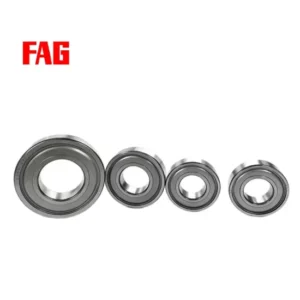


Product Details
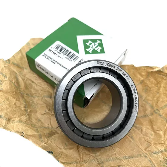
About This INA Bearing
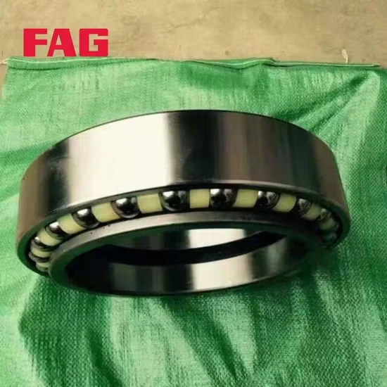
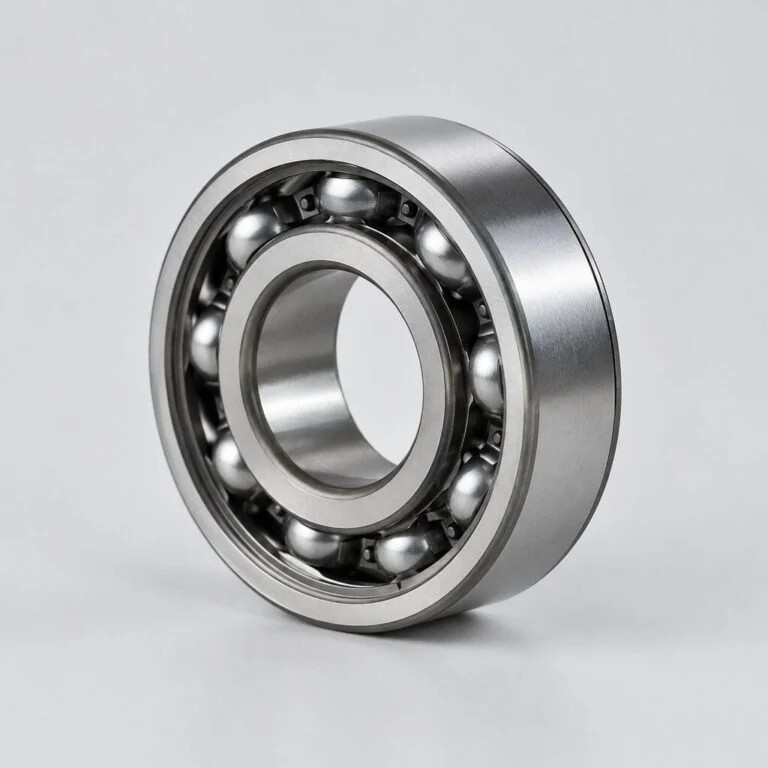
Cross-Reference Alignment — We verify the FAG B71902-E-T-P4s-Um angular contact ball bearing against OEM spindle requirements, meticulously matching dimensional tolerances, precision classes, and specific pairing configurations to completely prevent costly assembly mismatches during machine tool maintenance.
Technical Specifications
| Parameter | Value |
|---|---|
| Designation | B71902-E-T-P4s-Um FAG |
| Bearing Type | Angular Contact Ball Bearing |
| Precision Class | P4s (ISO) |
| Contact Angle | 25° |
| Material | Steel (hybrid ceramic variants available) |
| Origin | Jiangsu China |
Note: Suffixes B, T, and Um require manufacturer catalog confirmation for exact internal design and pairing specifics.
Application Suitability
| Industry | Typical Applications |
|---|---|
| Machine Tool Manufacturing | High-speed motorized spindles for CNC milling machines |
| Precision Engineering | Rotary tables and indexing heads requiring tight runout limits |
| Industrial Robotics | High-frequency articulation joints demanding positional accuracy |
Why Spindle Vibration Traces Back to the FAG B71902-E-T-P4s-Um angular contact ball bearing Suffixes
Precision pairing and exact contact angles dictate whether a high-speed spindle runs smoothly or seizes under thermal expansion.
Early in my career supporting machine tool spindles in West Africa, I swapped a specified P4s paired set for standard P5 singles to save time on a critical repair. The result was catastrophic vibration and a completely seized spindle shaft within hours of restarting the machine. Procurement engineers and maintenance planners often overlook that a slight deviation in suffix configurations leads to severe dynamic imbalance. This seemingly minor oversight turns a routine weekend maintenance task into an unplanned production halt, destroying expensive cutting tools and ruining the surface finish of precision aerospace components, causing massive financial losses.
Matching Spindle Dynamics with the FAG B71902-E-T-P4s-Um angular contact ball bearing
High-speed machining centers demand exceptional rotational accuracy and structural rigidity to maintain tight tolerances. The FAG B71902-E-T-P4s-Um angular contact ball bearing delivers the necessary 25° contact angle to effectively manage the complex combined radial and axial thrusts generated during heavy milling cuts. Our specialized engineering team cross-checks these specific suffix configurations against your detailed spindle drawings to ensure the preload and dimensional tolerances align perfectly with the original equipment manufacturer's exact design intent, preventing premature fatigue.
Navigating Thermal Growth and Lubrication in High-Frequency Machining
Spindle environments continuously subject internal components to intense localized heat and rapid acceleration cycles. As rotational speeds climb toward the limiting threshold, internal friction generates significant thermal growth that fundamentally alters internal clearance and contact stress distribution. Proper lubrication becomes absolutely critical; oil-air or advanced grease systems must be carefully selected based on the exact speed factor to prevent cage starvation. Furthermore, the 25° contact angle must be strictly maintained under dynamic load to prevent edge stressing, requiring rigorous adherence to mounting protocols and cleanroom standards to avoid microscopic particulate contamination.
Decoding the P4s Precision and 25° Contact Geometry
The P4s precision class ensures exceptionally tight dimensional and running accuracy, which is mandatory for minimizing runout in precision grinding and high-speed milling spindles. A 25° contact angle provides an optimal mechanical balance, offering substantially higher axial rigidity compared to 15° variants while maintaining acceptable radial load capacity for most machining operations. The construction is available in standard bearing steel or hybrid ceramic variants, providing the necessary core hardness and fatigue resistance required for continuous high-speed operation without spalling. Understanding these specific geometric and material parameters allows maintenance teams to accurately predict service intervals and avoid catastrophic runout deviations during critical finishing passes on expensive workpieces.
The Financial Impact of Compromised Spindle Tolerances
Installing a bearing with incorrect precision or mismatched pairing suffixes rarely causes immediate mechanical failure; instead, it initiates a destructive cascade of micro-vibrations. This degraded surface finish quality leads to scrapped workpieces and accelerated tool wear, long before the bearing itself physically fails or shows visible signs of damage. Ultimately, the hidden costs of unplanned downtime, ruined raw materials, and emergency air freight for replacement parts vastly outweigh the initial savings of sourcing non-compliant alternatives from unauthorized distributors.
Securing Authentic Spindle Components Through Rigorous Verification
Sourcing genuine high-precision components requires much more than just matching the part number printed on a cardboard label. We verify every FAG B71902-E-T-P4s-Um angular contact ball bearing through authorized channels, ensuring the P4s tolerance reports perfectly match the physical batch. Our technical team specifically checks the often-missed universal pairing and preload suffixes to prevent the exact assembly errors I encountered in the field. We consolidate mixed-brand spindle repair kits, providing full traceability documentation so your maintenance logs remain fully compliant with strict OEM warranty requirements and audit standards, giving you complete peace of mind.
Documentation & Authenticity
- Original factory batch traceability linking the P4s inspection report to the specific bearing set.
- Dimensional and running accuracy certificates confirming ISO P4s tolerances before dispatch.
- Official manufacturer app QR validation to guarantee the authenticity of the steel spindle components.
- Material certification verifying the metallurgical composition of the rings and rolling elements.
Storage, Handling & Mounting
- Keep the P4s matched set sealed in its original vacuum packaging until the exact moment of spindle assembly.
- Use lint-free cleanroom gloves when handling the 25° contact angle surfaces to prevent corrosive sweat transfer.
- Verify the universal pairing marks on the outer rings before pressing to maintain the factory preload configuration.
- Apply induction heating strictly within specified limits to avoid altering the dimensional stability of the precision steel races.
Preparing Your Spindle Data for Technical Review
To ensure accurate cross-referencing and reliable L10 life calculation, please provide the specific radial and axial load profiles along with the maximum operating speed of your spindle. Sharing the original equipment manufacturer's assembly drawings or the exact OEM part number allows our engineers to verify the required pairing configuration and preload class. This thorough technical review guarantees the proposed solution perfectly aligns with your machine's dynamic rigidity requirements and production schedules.
Frequently Asked Questions
Q: How do I verify the authenticity of this FAG spindle bearing through official channels?
A: You can authenticate the component by scanning the QR code on the packaging using the manufacturer's official mobile application. Additionally, we provide original factory batch traceability documents and P4s precision inspection reports that cross-reference the physical serial numbers, ensuring the steel bearing set is entirely genuine and untampered.
Q: What distinguishes the P4s precision class from standard P4 in ISO standards?
A: The P4s class specifies even tighter tolerances for running accuracy and dimensional stability compared to standard P4. This enhanced precision is specifically engineered for high-speed machine tool spindles where minimal runout is critical. It ensures the 25° contact angle maintains optimal load distribution under extreme rotational velocities without excessive heat.
Q: How does the 25° contact angle affect spindle load capacity and speed limits?
A: A 25° contact angle provides a balanced compromise between axial rigidity and radial load capacity.* milling operations better than a 15° design, while still permitting the high rotational speeds required for precision machining without generating excessive internal friction or thermal growth.
Q: What are the correct mounting procedures for maintaining the factory preload?
A: Mounting requires strict adherence to the pairing marks etched on the outer rings. The matched set must be installed in the exact sequence indicated by these marks to preserve the universal preload configuration. Using controlled induction heating and cleanroom environments prevents contamination and thermal distortion of the precision steel components.