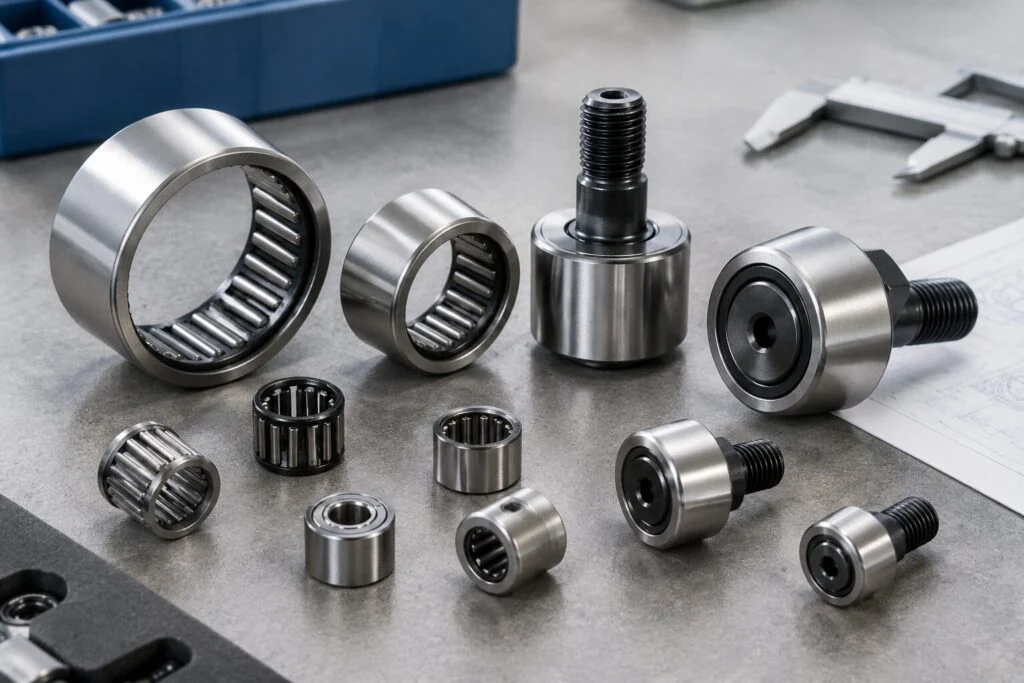
Drawn Cup Needle Bearings Installation Guide – Wholesale Supplier
Hammering drawn cup needle bearings into place is the fastest way to destroy them.
Correct installation of drawn cup needle bearings requires dedicated press-fit tools to apply uniform axial force, preventing thin-wall deformation and ensuring optimal lifespan. Direct impact methods like hammering cause immediate loss of roundness, leading to premature failure regardless of bearing quality.
I still remember the look on a client’s face in Hanover. He slammed a box of bearings on my desk, insisting they were out-of-round from the factory. The outer rings were visibly distorted. I pulled out a loupe and pointed to the jagged indentations along the edge. These weren’t manufacturing defects; they were hammer marks. Someone had tried to force the bearing into a housing using a steel punch and a mallet. The thin-walled design of drawn cup needle bearings makes them incredibly space-efficient, but it also makes them vulnerable to radial impact. Without proper tooling, the metal buckles before it seats. This isn’t just a theoretical risk; it is the most common cause of early failure in applications ranging from automotive transmissions to agricultural gearboxes. [NEED_CITE: common causes of bearing failure during mounting per ISO 15243]
Understanding why these components fail during assembly is the first step toward fixing the process. The issue isn’t usually the bearing itself, but the method used to put it in place.
Why Drawn Cup Bearings Are Prone to Installation Damage?
The structural design of drawn cup needle bearings is their greatest strength and their biggest weakness during installation. Unlike standard roller bearings with thick, machined outer rings, drawn cups are formed from thin sheet steel. This allows for a high load capacity in a minimal radial space, which is why they are ubiquitous in compact machinery. However, this thin wall lacks the rigidity to withstand uneven forces.
When a technician strikes the bearing directly, the force is not distributed evenly across the circumference. Instead, it concentrates at the point of impact. This localized stress exceeds the yield strength of the thin steel, causing permanent deformation. The bearing loses its circular shape, becoming oval or irregular. Once installed in this state, the rolling elements cannot move freely. Friction increases, heat builds up, and the bearing seizes long before its rated life is reached.
In many workshops, the assumption is that a tight interference fit requires brute force. This is a dangerous misconception. A proper interference fit relies on precise dimensional tolerances between the bearing outer diameter and the housing bore. The goal is to slide the bearing in with controlled pressure, not to beat it into submission. [NEED_CITE: principles of interference fits and housing tolerances]
I have seen this scenario play out in textile mills where vibration levels spiked after maintenance. The root cause was never the bearing quality, but the installer’s habit of using a screwdriver and hammer to tap the bearing into place. The resulting misalignment caused excessive noise and wear on the shaft. Switching to proper press-fit techniques eliminated these issues entirely. The key is recognizing that the thin wall needs support from the inside and outside during the entire insertion process.
Essential Tools for Proper Press-Fitting
You cannot install drawn cup needle bearings correctly with generic workshop tools. A hammer, a punch, or a pair of pliers will almost certainly damage the component. The correct approach involves using tools that convert manual or hydraulic force into uniform axial pressure.
The primary tool required is an arbor press or a hydraulic press capable of delivering smooth, controlled force. Hand presses are often sufficient for smaller bearings, while larger industrial units may require hydraulic assistance. The critical component, however, is the mandrel or sleeve adapter. This tool must match the inner diameter of the bearing precisely. It transfers the pressing force from the machine to the bearing’s inner ring or rollers, bypassing the fragile outer cup entirely.
| Tool Type | Function | Risk if Misused |
|---|---|---|
| Arbor Press | Applies uniform axial force | Minimal if aligned correctly |
| Sleeve Adapter | Distributes force to inner ring | None if sized correctly |
| Hammer | Direct impact | High risk of outer ring deformation |
| Generic Punch | Concentrated force | High risk of cage damage |
Using a sleeve that is too large can crush the rollers or cage inside the bearing. Using one that is too small may slip and score the inner surface. The ideal adapter matches the bearing’s internal dimensions closely, ensuring that the force is applied only to the solid structural parts of the bearing. [NEED_CITE: SKF technical mounting manuals for needle roller bearings]
Sourcing high-precision drawn cup needle bearings from reliable global suppliers ensures dimensional consistency, which makes proper installation achievable. When the bearing dimensions are within strict tolerances, the press-fit process becomes predictable. Inconsistent quality from unknown sources can lead to variable interference fits, making even the best tooling ineffective. This is why established distributors prioritize brands with rigorous quality control, such as INA or NSK, alongside verified domestic lines.
In a recent case involving an agricultural gearbox manufacturer, switching from manual hammering to dedicated arbor presses reduced their rejection rate significantly. The technicians initially resisted the change, citing speed, but the reduction in downtime due to misaligned replacements quickly proved the value of the right tools. The initial investment in proper tooling pays for itself by eliminating the cost of failed assemblies and warranty claims.
Step-by-Step Installation Guide
Proper installation is a systematic process that requires preparation and attention to detail. Rushing through any step can compromise the entire assembly. Here is the proven methodology for installing drawn cup needle bearings without causing damage.
-
Preparation and Inspection: Clean the housing bore and the shaft thoroughly. Any dirt or debris can cause misalignment or damage during pressing. Check the housing bore for burrs or scratches. Verify that the bearing matches the part number and inspect it for any visible shipping damage. [NEED_CITE: ISO standards for bearing mounting cleanliness]
-
Tool Selection: Choose a mandrel or sleeve that matches the bearing’s inner diameter. Ensure the press plates are parallel to avoid tilting *e lightly with a thin oil to reduce friction, unless the application specifies a dry fit.
-
Alignment: Place the bearing into the housing entrance. Ensure it is square with the bore. Misalignment at this stage will cause the bearing to bind and potentially crack the housing or deform the cup. Use a dial indicator if necessary to confirm perpendicularity.
-
Pressing: Apply steady, slow pressure using the arbor press. Do not jerk or impact the handle. Watch the bearing as it enters the housing. If resistance increases suddenly, stop immediately. Forcing it further can cause catastrophic failure. The bearing should seat smoothly against the shoulder of the housing.
- Post-Installation Check: Once seated, rotate the shaft by hand to ensure free movement. Check for any binding or unusual noise. Measure the outer diameter if accessible to confirm no deformation has occurred.
A European wind farm operator once reported inconsistent performance in their gearbox repairs. Upon review, we found that the installation team was skipping the alignment check, assuming the press would correct any angle. This led to uneven loading and premature wear. Implementing a strict alignment protocol resolved the issue. The key takeaway is that patience during the pressing phase prevents costly rework later.
Common Mistakes to Avoid
Even with the right tools, errors can occur. Awareness of these common pitfalls is essential for maintaining high assembly standards.
Hammering Directly: As mentioned earlier, striking the outer ring directly is the most destructive mistake. It causes immediate deformation and compromises the bearing’s structural integrity. Never use a hammer on a drawn cup bearing.
Ignoring Housing Tolerances: The housing bore must be within specified tolerance limits. If the bore is too large, the bearing will spin; if too small, it will not seat properly. Checking the bore diameter before installation is crucial. [NEED_CITE: housing bore tolerance classes for needle bearings]
Misalignment During Pressing: Til*. This can crack the thin outer ring or damage the housing. Always ensure the bearing is square before applying pressure.
Using Incorrect Adapters: An adapter that contacts the cage or rollers instead of the inner ring can destroy the bearing internally. Always verify that the tool engages the solid parts of the bearing.
In the automotive transmission sector, a shift from manual assembly to automated press-fitting with proper sensors reduced noise and vibration failures. The system detected misalignment instantly, preventing defective units from moving down the line. For smaller shops, visual inspection and careful manual pressing can achieve similar results if the technicians are trained to recognize the signs of improper installation.
Conclusion
Proper installation is just as critical as bearing quality.
Installing drawn cup needle bearings correctly requires more than just force; it demands precision, the right tools, and a respect for the component’s thin-walled design. By avoiding direct impact, using appropriate press-fit adapters, and ensuring strict alignment, you can prevent deformation and extend the service life of your machinery. The difference between a successful assembly and a premature failure often comes down to the method used in those first few seconds of installation.